I'm making a WiFi GameBoy Cartridge!
It works, which is cool!
It's not finished, which is ok.
And Sebastian Staacks just posted a nice write up about finishing his own, which makes me a bit sad, but they have enough differences to be interesting.
So here's mine!
I was hoping to have a completed PCB and a demo before writing about it, but since I got scooped maybe I can ride some coattails! Unfortunately I'm trying to get this out fast so that I hopefully don't lose all my motivation and I'm not practiced at writing, soooooo this is going to be rough... Also my site isn't ready. Oh well!
What is it?
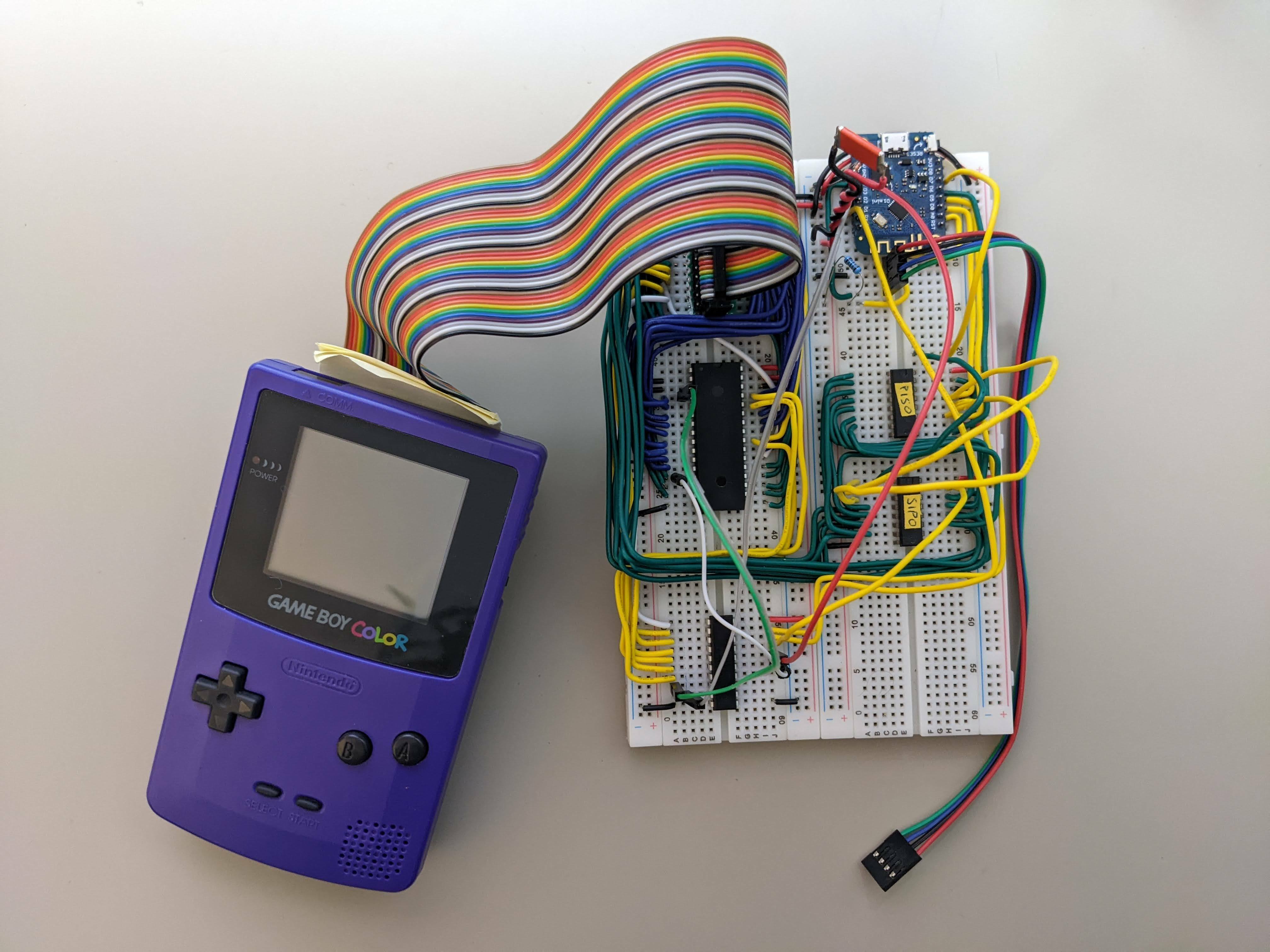
It's a GameBoy "cartridge" that can connect to WiFi. When I started this project I also started watching Ben Eater's videos building a breadboard CPU so that's why it looks the way it does.
My goal was to build a cartridge that looked exactly like a normal GameBoy game but could connect to the internet. Exactly like Sebastian did!
How does it work?
In some important ways it works the same as Sebastian's does. I have a ROM chip that has GameBoy code and images, I have an ESP8266 to do the WiFi, I have some hardware logic to map the ESP to a magic GameBoy memory address, and I have a big honkin capacitor to keep the ESP from overloading the GameBoy's power system.
What's different?
There are a few small differences and a few bigger ones.
Small differences
-
I'm using flash memory for my ROM. I think it was cheaper?
-
I went with a 2200uF capacitor for power. I'll have to try smaller values now because the 2200uF tantalum capacitor is over $10 (CAD). I got the 2200uF from a YouTube video about evening out the peaks from an ESP8266. The link to the video that I wrote down (on paper) doesn't work so either it's gone or I wrote it wrong.
-
I'm using a wemos D1 mini for my ESP. My plan is to use a more compact ESP module and a 3.3V regulator once I get to the PCB stage. The wemos is just very convenient for now.
-
I've mapped the ESP to the GameBoy's cartridge RAM address space instead of a ROM address. I wasn't including RAM in my cartridge and this meant I could use the same address for sending to and reading from the ESP.
Bigger differences
The data channel
The biggest difference is that I'm not connecting 8 of the ESP's GPIO pins directly to the data bus (with a bus transceiver). Instead I'm using 2 shift registers:
- A CD74HCT597, parallel-in-serial-out (PISO), to capture data from the GameBoy to feed it to the ESP.
- A CD74HC4094, serial-in-parallel-out (SIPO), to get data from the ESP and store it until the the GB is ready to read it.
The reason I went with shift registers is because I wanted to avoid the issue of matching the GameBoy's timing as much as possible and to use fewer of the ESP's pins. From Sebastian's description of the timing issues, and seeing as I don't have an oscilloscope, I think I made the right choice for me.
The reason I chose those particular shift registers is because I didn't know what I was doing and I mostly picked at random!
I have them hooked up to the ESP's SPI bus with 2 additional ESP pins setup as interrupts, one to tell the ESP that the GameBoy wrote some data to the PISO and the other to tell it the GameBoy read from SIPO. This setup gave me reasonable speed. In one test I was able to have the GameBoy copy a value from its memory over to the ESP 10 times in a loop. Something like:
    ld b, 10
    ld hl, $C005
.write10
    ld a, [hli]
    ld [rESP], a
    dec b
    jr nz .write10
(basically a for loop, if you don't read assembly)
Where I have rESP defined as rESP EQU $A000. $A000 is the memory address I use to communicate with the ESP.
Getting fast two-way data was a bit of a problem though since the two shift registers need different SPI modes and switching the modes caused too much of a delay to be work well. To overcome this problem I used one of the ESP's GPIOs as a "ready" flag that the GameBoy could read from the least significant bit at address $B000. A 0 (the ready pin is low) meant the ESP wasn't ready for data. A 1 (the ready pin is high) meant the ESP was ready. In my tests I would also have the ESP load up the SIPO before setting ready to 1.
Surprisingly this didn't work!
At least when I had code that looked like:
    ld [rESP], a
.wait
    ld a, [rESP_READY]
    and 1
    jr nz, .wait
    ld a, [rESP]
It turns out that the ESP couldn't get the ready pin to 0 before the GameBoy read it! I was setting it to 0 as the first step in my interrupt handler. I really didn't expect it to miss the timing.
So I switched to inverting the ready pin to indicate the ESP is ready. This means that the ESP doesn't need to do anything to indicate it isn't ready and it can definitely do nothing faster than the GameBoy! Of course it means the GameBoy needs to keep track of the last value of the ready flag, which could get annoying later.
Logic hardware
In order to control the shift registers and ESP interrupts I need to detect specific values on some of the cartridge's address pins and control pins. Specifically I need to be watching address pins A12-15 (0 based numbering) and the WR, RD, and CS pins. When those pins have the right values I'll either:
- latch the data pins into the PISO register and trigger the interrupt pin to tell the ESP it has data to look at
- set the output enabled on the SIPO so the GB gets the data from it and trigger the interrupt pin to tell the ESP it can send another byte
- get the value of the ESP's ready pin onto the data pin D0
Sebastian solved his similar control problem with logic gate. I almost did that, in fact I bought a bunch of logic gates. I think I got lucky though, because I also bought an ATF16V8B programmable logic device (PLD)! This is a little chip with a bunch of logic gates inside and you can program it to work like an arbitrary logical expression. I bought it because I didn't know any better, it sounded like it would be really handy, and because Ben Eater's videos got me over-confident enough to think I could program anything using an arduino. I couldn't!
But luck struck some more because it turns out that programming a flash memory chip with an arduino is a pain in the butt! So instead of turning that into a project I went and bought a TL866II Plus chip programmer to program my flash memory. And it just so happens that it can also program the ATF16V8B! It took a while to get it all working, but now I have the one chip to do all my hardware logic!
Another detail is that when the GameBoy is reading the ready pin, I'm actually only driving D0 and leaving all the other data pins floating. This isn't a good thing to do, but nothing has broken yet. My feeling/guess is that the GameBoy hardware would have protection against a truly floating data pin but I haven't checked...
Too much power
This is one area where I'm maybe pushing my luck. You see, it turns out that the ESP's GPIO pins are apparently 5V tolerant. So I don't step any of the logic down to 3.3V feeding into the ESP. Also all the chips the ESP talks to will happily register 3.3V as high (I don't remember if I checked this when buying components). It's possible that the GameBoy might not be happy with 3.3V but the ESP never talks directly to the GameBoy. Even the ESP's ready pin goes through the PLD. This saved me a bunch of circuitry and components and so far nothing's exploded!
So what's the state of the project?
Well, it's not done...
It's actually working though, and I've run some simple tests of communicating between the GameBoy and the ESP. I've also done some VERY simple demos using the WiFi (I made a cloud based increment operator).
I was just getting started designing the PCB, but I've never done any PCB design before so who knows how many mistakes I'll make with that.
So best case scenario, if I get enough time to work on the PCB, don't make any mistakes with it, and don't destroy any of my components when soldering them I could have the hardware done in a month. That is very unrealistic!
I'll keep chugging along though. Hopefully this will be a good kick in the pants to get me actually making content about it regularly!